
Industrial integer linear programs with Decoded Quantum Interferometry
Basic Information
- Paper: Towards Solving Industrial Integer Linear Programs with Decoded Quantum Interferometry
- arXiv ID: 2509.08328v1
- Submission Date: September 10, 2025
Core contribution
- Converting the ILP into instances of max-XORSAT
- Developing a detailed quantum circuit implementation for belief propagation, a heuristic algorithm for decoding LDPC codes.
1.Converting the ILP into instances of max-XORSAT
1.1: Convert the constraints of Integer Linear Programming (ILP) into max-XORSAT
Suppose we have this constraints: $a_1 x_1 + \cdots + a_n x_n > b$ $(x_i \in {0,1})$ $(a_i, b \in \mathbb{Z})$, and we need to convert it into a form that can be processed by max-XORSAT.
We first need to convert every $a_i$ into its binary representation. For example, $5$ becomes $101_2$.
Thus each term can be expanded as:
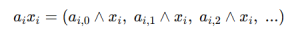
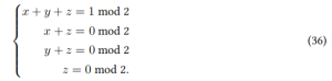
At this point each bit is expressed as a Boolean AND. However, max-XORSAT cannot contain AND operations, so we must introduce a gadget. According to the paper (Eq.~(36)), the gadget enforces the relation $z = x y$ using several XOR equations only.
Next, since we need to add many binary numbers, and because there are carries, binary addition is not just a simple XOR operation. For example, in binary we have $1 + 1 = 10_2$, whereas $1 \oplus 1 = 0$. For binary addition, the sum bit and the carry bit are given as follows.
Sum bit:
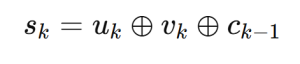
Carry bit:
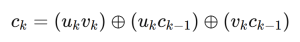
We can see that there are Boolean AND terms here as well, each of these ANDs can be eliminated using the same gadget as before.
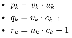
The carry operation also requires a gadget. For each carry bit we must introduce three product variables
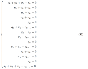
The full max-XORSAT instance can then be expressed as (all equations in mod 2)
1.2: Convert the ILP objective function into the max-XORSAT form
Conceptually, this procedure is a binary search. We fix a candidate threshold $T$ and ask:
Does the ILP $c(T)$ have a feasible solution?
- If it has a feasible solution, then the optimal value satisfies $\ge T$.
- If it does not have a feasible solution, then the optimal value is $< T$.
By performing a binary search (or iterative updates) on $T$, we eventually determine the optimal objective value.
2.The complete, executable quantum circuit–level implementation of DQI
Here I describe only the quantum circuit for the decoder. All other circuit components can be found in the paper “Optimization by Decoded Quantum Interferometry”.
There are five registers in total:
- error register $y$ (with $m$ qubits)
- syndrome register $s_0$ (with $n$ qubits) In addition, two auxiliary registers are introduced
- hamming register: stores the Hamming weight, i.e., how many $1$’s appear in the relevant syndrome
- comparator register: determines whether the Hamming weight reaches the flipping threshold
- filp register
For each constraint (i.e., for each row of $B$):
- Find the indices of the constraints that related with this variable.
- Perform the Hamming-weight computation:
for every constraint $i$ such that $B[i,j] = 1$ and the corresponding syndrome bit is $1$, apply a controlled “$+1$” operation to the hamming register, apply a controlled “$+1$” operation on the hamming register.
Next we define the threshold as the degree of the variable in the matrix B, i.e., the number of constraints to which the variable is connected.
Then use Qiskit’s IntegerComparator to compare:
Hamming weight ≥ threshold ?
If the condition holds, the comparator circuitry applies a controlled operation that sets the comparator’s first qubit to $\lvert 1 \rangle$. This output qubit is then used as the control to write the corresponding bit in the flip register, i.e.,$\text{flip}_i[k] = 1$.
This rule requires that all relevant constraints indicate that the bit is wrong before a flip is applied. In other words, a message bit is flipped only if every constraint involving that bit votes for flipping it.
The new syndrome $s_i$ is
$$ s_i = B^{\mathsf T}\bigl( y \;\oplus\; \mathrm{flip}_1 \;\oplus\; \mathrm{flip}_2 \;\oplus\; \cdots \;\oplus\; \mathrm{flip}_i \bigr). $$
However, we must not update the existing syndrome and error registers in place.
Because the circuit has to remain unitary (reversible), the updated syndrome must be computed into an extra register, rather than overwriting the original contents directly.
We repeat this procedure for the next iteration, but we still do not update the error register during the intermediate steps. Only after all iterations are completed do we update the error register in one shot, using the accumulated flips:
$$ y \;\leftarrow\; y \;\oplus\; \mathrm{flip}_1 \;\oplus\; \mathrm{flip}_2 \;\oplus\; \cdots \;\oplus\; \mathrm{flip}_T . $$
Finally, after committing the update, we run the entire circuit in reverse to uncompute and clear all ancilla registers.